生活中常用的电力有交流(AC)和直流(DC)两种。交流电主要从公用电网中获得,直流电主要从蓄电池或干电池中获得。然而,从这些电源中获得的电力往往不能直接满足用电需求,需要利用电力电子拓扑进行电力变换。你可能知道电力变换分为交流变直流(AC-DC)、直流变交流(DC-AC)、直流变直流(DC-DC)以及交流变交流(AC-AC)四类。那么,它们之间到底是如何变换的呢?
There are two kinds of power commonly used in life: AC (AC) and DC (DC). Alternating current is mainly obtained from the public grid, and direct current is mainly obtained from batteries or dry batteries. However, the power obtained from these sources often cannot directly meet the electricity demand, and the power electronic topology needs to be used for power transformation. You may know that power conversion is divided into four categories: AC to DC (AC-DC), DC to AC (DC-AC), DC to DC (DC-DC), and AC to AC (AC-AC). So, how do they change?
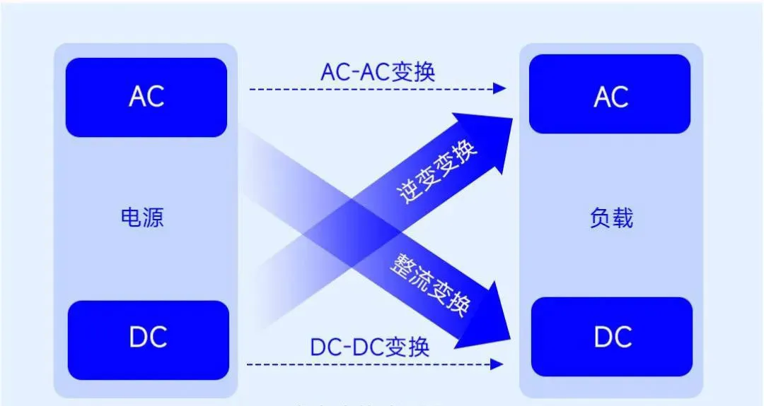
电力变换类型图
Power conversion type diagram
本文揭秘电力电子技术如何实现电能的变换和控制。为了能让大家更清楚直观地理解,下文将对电力变换类型进行介绍,并针对常用电力变换电路的工作原理进行分析。
This paper reveals how to transform and control electric energy by power electronics technology. In order to allow everyone to understand more clearly and intuitively, the following will introduce the types of power conversion, and analyze the working principle of common power conversion circuits.
直流-直流变换/ Dc-dc transformation
直流-直流变换电路的功能是将一种直流电变为另一种直流电。根据电路结构不同,直流-直流变换电路分为非隔离型DC-DC电路以及隔离型DC-DC电路。非隔离型DC-DC电路主要实现直流的直接变换,又分为升压(Buck)、降压(Boost)以及升降压(Buck-Boost)电路,其电路结构如图所示。其中降压/升压电路(Buck/Boost)应用最为广泛。
The function of a DC-DC conversion circuit is to change one type of direct current into another. According to the different circuit structure, DC-DC conversion circuit is divided into non-isolated DC-DC circuit and isolated DC-DC circuit. The non-isolated DC-DC circuit mainly realizes the direct conversion of DC, and is divided into Buck (Boost), Boost (boost) and buck-boost (buck-boost) circuits, and its circuit structure is shown in the figure. The Buck/Boost circuit is the most widely used.
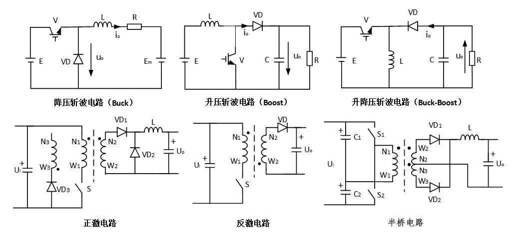
常用非隔离型DC-DC电路图
Non-isolated DC-DC circuit diagrams are commonly used
以Boost电路为例,对非隔离型DC-DC电路的工作原理进行分析:首先假设电路中电容值与电感值很大。当可控开关V处于通态时,电源E向电感L充电,同时电容C向负载R供电,由于电容值很大,所以输出电压uo基本保持为恒定值;当V处于断态时,电源E和电感L共同向电容C充电并向负载R供电。Boost电路的输出波形如图所示。
Taking Boost circuit as an example, the working principle of non-isolated DC-DC circuit is analyzed. First, it is assumed that the capacitance value and inductance value in the circuit are large. When the controllable switch V is in the on state, the power supply E charges the inductor L, while the capacitor C supplies power to the load R. Due to the large capacitance value, the output voltage uo is basically maintained at a constant value. When V is in the off state, the power supply E and the inductor L jointly charge the capacitor C and supply the load R. The output waveform of the Boost circuit is shown in the figure.

Boost电路输出波形
Boost circuit output waveform
隔离型DC-DC电路主要实现直-交-直变换,电路中包含交流环节且多采用变压器进行输入输出隔离。隔离型DC-DC电路中推挽、反激、移相全桥拓扑、LC拓扑以及LLC拓扑被广泛应用于各类工业电源中。
The isolated DC-DC circuit mainly realizes DC-AC-DC transformation, and contains AC link in the circuit and uses transformer for input and output isolation. Push-pull, flyback, phase-shift full-bridge topology, LC topology and LLC topology in isolated DC-DC circuits are widely used in various industrial power supplies.
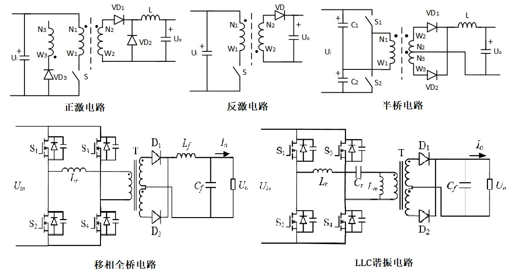
隔离型DC-DC电路结构图
Isolated DC-DC circuit structure diagram
各类隔离型DC-DC变换电路的优缺点、功率范围以及应用领域如下表所示。
The advantages and disadvantages, power ranges and application fields of various isolated DC-DC conversion circuits are shown in the following table.
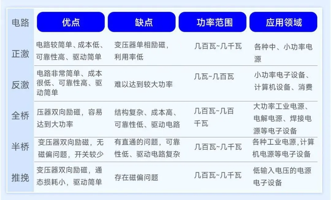
常用隔离型DC-DC变换电路对比表
Comparison table of commonly used isolated DC-DC conversion circuits
交流-直流变换/ Ac-dc transformation
交流-直流变换又称为整流。整流电路按输入交流的相数可分为单相整流与多相整流;按照构成器件可分为全控整流、半控整流以及不控整流;按电路结构可分为桥式整流与零式整流。常用的整流电路主要有半波整流电路、全波整流电路、桥式整流电路以及倍压整流电路。其基本的电路结构如图所示。
The AC-DC transformation is also called rectification. The rectifier circuit can be divided into single-phase rectifier and polyphase rectifier according to the phase number of input AC. According to the component, it can be divided into full control rectifier, half control rectifier and non-control rectifier. According to the circuit structure, it can be divided into bridge rectifier and zero rectifier. The common rectifier circuit mainly includes half wave rectifier circuit, full wave rectifier circuit, bridge rectifier circuit and voltage doubling rectifier circuit. Its basic circuit structure is shown in the figure.
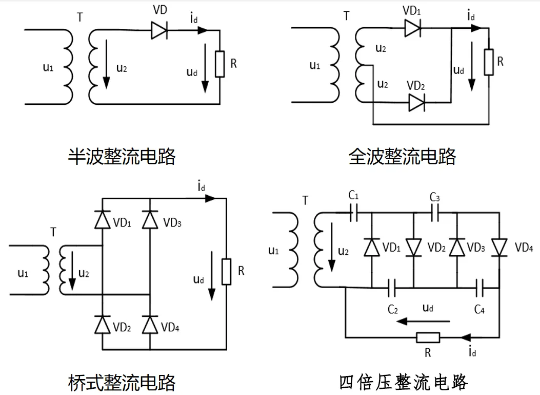
常用的不控整流电路结构图以单相桥式不控整流电路为例对整流电路的工作原理进行分析。单相桥式不控整流电路由四个整流器件构成,其中VD1与VD4构成一组桥臂,VD2与VD3构成另一组桥臂。0-t1:输入电压正半周,VD1、VD4串联承受正向电压导通,电流经VD1- R-VD4流动,输出电压按照正弦规律变化;t1-t2:输入电压负半周,VD2、VD3串联承受正向电压导通,电流经VD3- R-VD2流动,输出电压按照正弦规律变化;单相桥式不控整流电路的输出电压波形如图所示。
The structure diagram of common uncontrolled rectifier circuit is used to analyze the working principle of single-phase bridge uncontrolled rectifier circuit. The single-phase bridge uncontrolled rectifier circuit is composed of four rectifier devices, wherein VD1 and VD4 constitute a group of bridge arms, and VD2 and VD3 constitute another group of bridge arms. 0-t1: The input voltage is positive for half a cycle, VD1 and VD4 are connected in series by the forward voltage, the electricity flows through VD1-R-VD4, and the output voltage changes according to the sine law; t1-t2: The input voltage is negative for half a cycle, VD2 and VD3 are subjected to positive voltage conduction in series, the electricity flows through VD3-R-VD2, and the output voltage changes according to the sine law; The output voltage waveform of single-phase bridge uncontrolled rectifier circuit is shown in the figure.
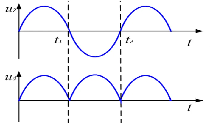
单相桥式整流电路输出波形图可控整流采用的功率器件均为可控器件,如晶闸管、IGBT等。可控整流电路可以通过开关器件的导通、关断来调节整流输出电压大小。常用的可控整流电路有三相桥式PWM整流电路与Boost-PFC整流电路,其电路结构如图。
The power devices used in controllable rectification are all controllable devices, such as thyristors, IGBTs, etc. The controllable rectifier circuit can adjust the output voltage of the rectifier by switching the device on and off. Commonly used controlled rectifier circuits include three-phase bridge PWM rectifier circuit and Boost-PFC rectifier circuit, whose circuit structure is shown in the figure.
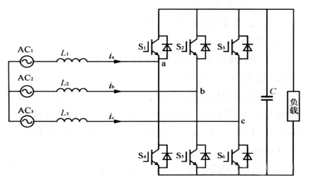
三相桥式PWM整流电路
Three-phase bridge PWM rectifier circuit
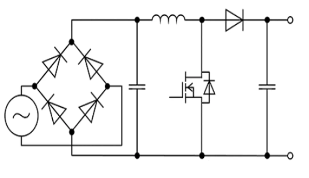
Boost-PFC整流电路可控整流电路结构图整流电路是电力电子电路中出现和应用最早的形式之一,它的作用是将交流电能变为直流电能供给直流用电设备。整流电路的应用十分广泛,例如直流电动机、电镀电解电源、同步发电机励磁、通信系统电源等。电力电子技术早期为整流器时代,后期则进入逆变器时代,下面对逆变变换进行介绍。
Boost-PFC rectifier circuit Controlled rectifier circuit structure diagram Rectifier circuit is one of the earliest forms of power electronic circuits, its role is to convert AC electrical energy into direct current power to supply DC electrical equipment. Rectifier circuit is widely used, such as DC motor, electroplating electrolytic power supply, synchronous generator excitation, communication system power supply and so on. In the early stage of power electronic technology, the rectifier era, the later stage into the inverter era, the inverter transformation is introduced below.
直流-交流变换/ Dc-ac transformation
与整流相对应,直流-交流变换又称为逆变。当交流侧接有电源时(接入电网)为有源逆变,交流侧直接连接负载时为无源逆变。实际应用中,常用的逆变电路为全桥逆变电路,电压型全桥逆变电路的结构如图所示。
Corresponding to rectification, DC-AC transformation is also called inverter. When the AC side is connected to the power supply (connected to the power grid), it is an active inverter. When the AC side is directly connected to the load, it is a passive inverter. In practical application, the commonly used inverter circuit is the full-bridge inverter circuit, and the structure of the voltage-type full-bridge inverter circuit is shown in the figure.
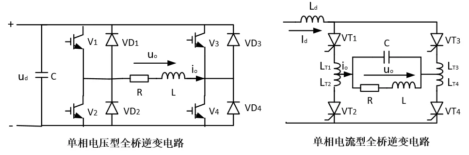
电压型全桥逆变电路结构图
Voltage type full bridge inverter circuit structure diagram
以单相电压型全桥逆变电路为例对逆变电路的工作原理进行分析。电路中两个桥臂为方向臂,另两个桥臂为斩波臂,这里V1、V2为方向臂,V3、V4为斩波臂。当调制信号ur>0,V1导通而V2关断,输出平均电压大于零;当调制信号ur<0,V1关断而V2导通,输出平均电压小于零;当ur>uc时,V4导通而V3关断;当ur<uc时,v3导通而v4关断。电路的输出电压波形如图所示。单相电压型全桥逆变电路输出波形图逆变电路在电力电子电路中占有十分突出的位置,电路在工作过程中会不断发生电流从一个支路向另一个支路的转移,即换流过程。在实际应用中,蓄电池、干电池、太阳能电池等直流电源若需要向交流负载供电时,就需要逆变电路。此外,交流电机调速用变频器、不间断电源、感应加热电源等电力电子装置的电路核心都是逆变电路。<uc时,v3导通而v4关断。电路的输出电压波形如图所示。
The principle of inverter circuit is analyzed by taking single-phase voltage type full-bridge inverter circuit as an example. In the circuit, two bridge arms are directional arms, and the other two bridge arms are chopper arms, where V1 and V2 are directional arms, and V3 and V4 are chopper arms. When the modulated signal ur>0, V1 is on and V2 is off, and the average output voltage is greater than zero; When the modulated signal ur<0, V1 is off and V2 is on, and the average output voltage is less than zero; When ur>uc, V4 is on and V3 is off. When ur
交流-交流变换/ Ac - AC transformation
交流-交流变换电路可以是对交流电的电压与电流幅值进行变换(交流调幅),也可以是对交流电的频率进行变换(交流调频),还可以是对交流电的相位进行变换(交流调相)。其中交流调幅主要应用于变压器以及异步电机软起动中。交流调频在变频器中应用广泛,而交流调相在实际中应用较少。交流变频电路分为直接变频电路(交流-交流)与间接变频电路(交流-直流-交流)。直接变频电路主要用于500kW以上的大功率、低转速的电动机调速系统中,如鼓风机、矿山破碎机以及磨球机等。
Ac-ac conversion circuit can be the conversion of the voltage and current amplitude of the alternating current (AC amplitude modulation), it can also be the conversion of the frequency of the alternating current (AC frequency modulation), and it can also be the phase of the alternating current (AC phase modulation). Ac AM is mainly used in transformer and induction motor soft start. Ac frequency modulation is widely used in inverter, but AC phase modulation is rarely used in practice. Ac frequency conversion circuit is divided into direct frequency conversion circuit (AC-AC) and indirect frequency conversion circuit (AC-DC-AC). The direct frequency conversion circuit is mainly used in the motor speed regulation system with high power and low speed above 500kW, such as blowers, mine crushers and ball grinding machines.
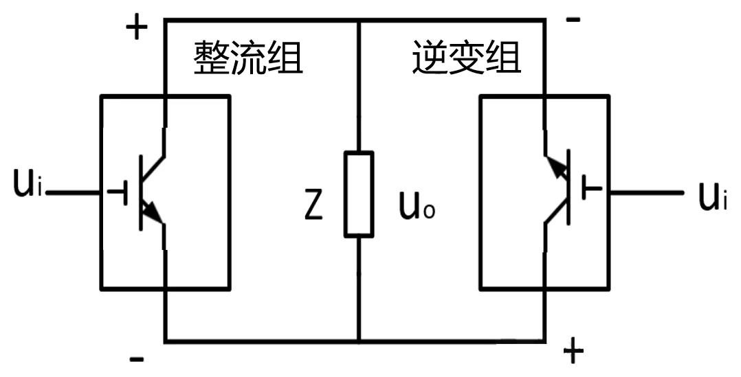
单相交流变频电路结构图
Single-phase AC frequency conversion circuit structure diagram
经过上述的介绍,想必大家对各类电力变换电路的工作原理及应用场景有了初步的了解。在实际应用中,各类开关电源是电力电子技术的主要应用场景。按照控制信号不同开关电源可分为模拟电源与数字电源。其中数字电源由于性能好、可靠性高、设计灵活等优势被广泛应用。
After the above introduction, we must have a preliminary understanding of the working principles and application scenarios of all kinds of power conversion circuits. In practical applications, various switching power supplies are the main application scenarios of power electronics technology. According to the different control signal switching power supply can be divided into analog power supply and digital power supply. Digital power supply is widely used because of its good performance, high reliability and flexible design.